
'A' SERIES
Firefighter Smoke Control Station (FSCS) / Smoke Purge System
UUKL & UUKL7 (Canada) listed.
California State Fire Marshal listed.
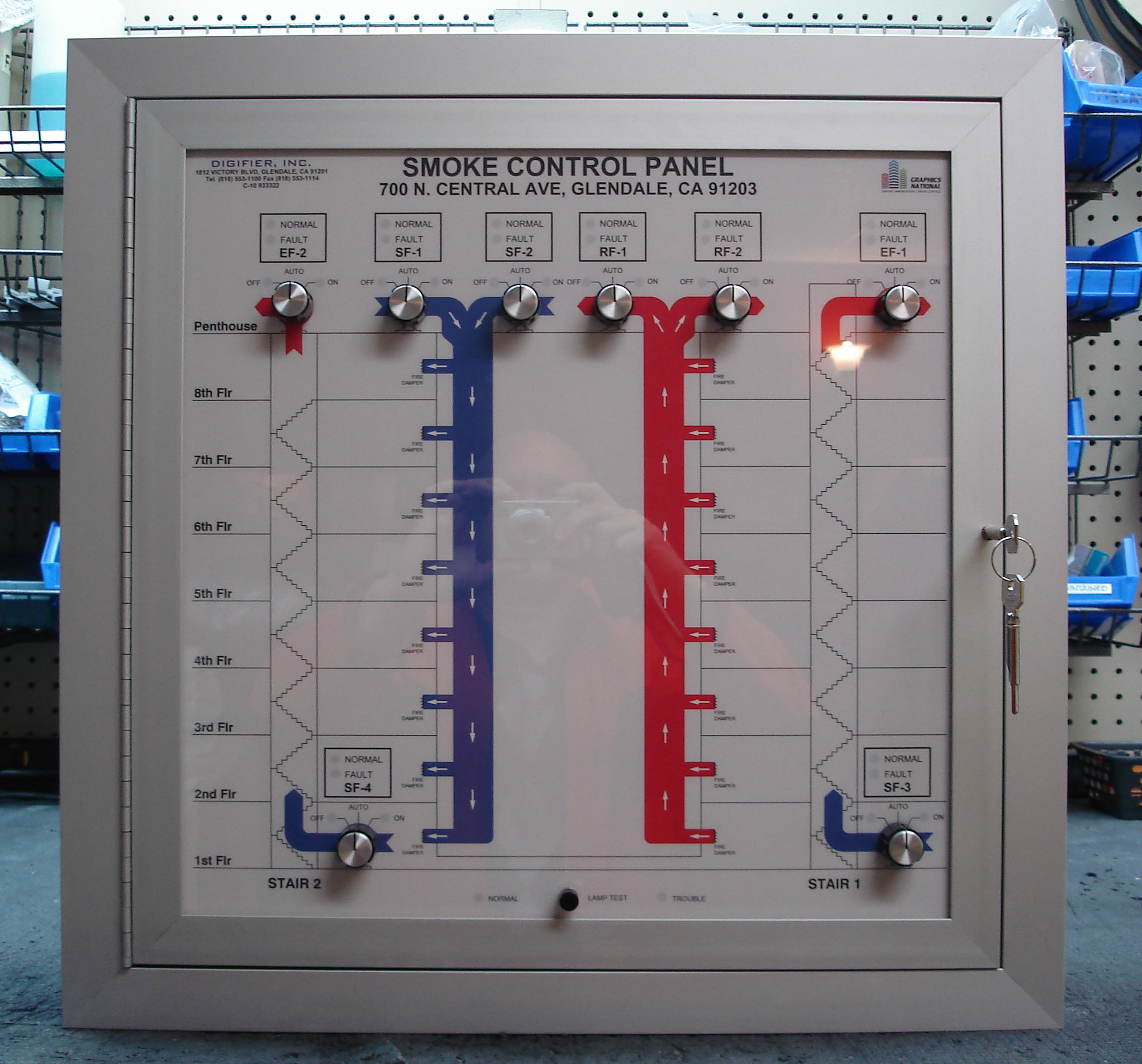
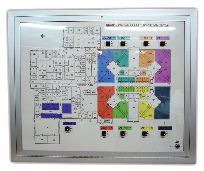


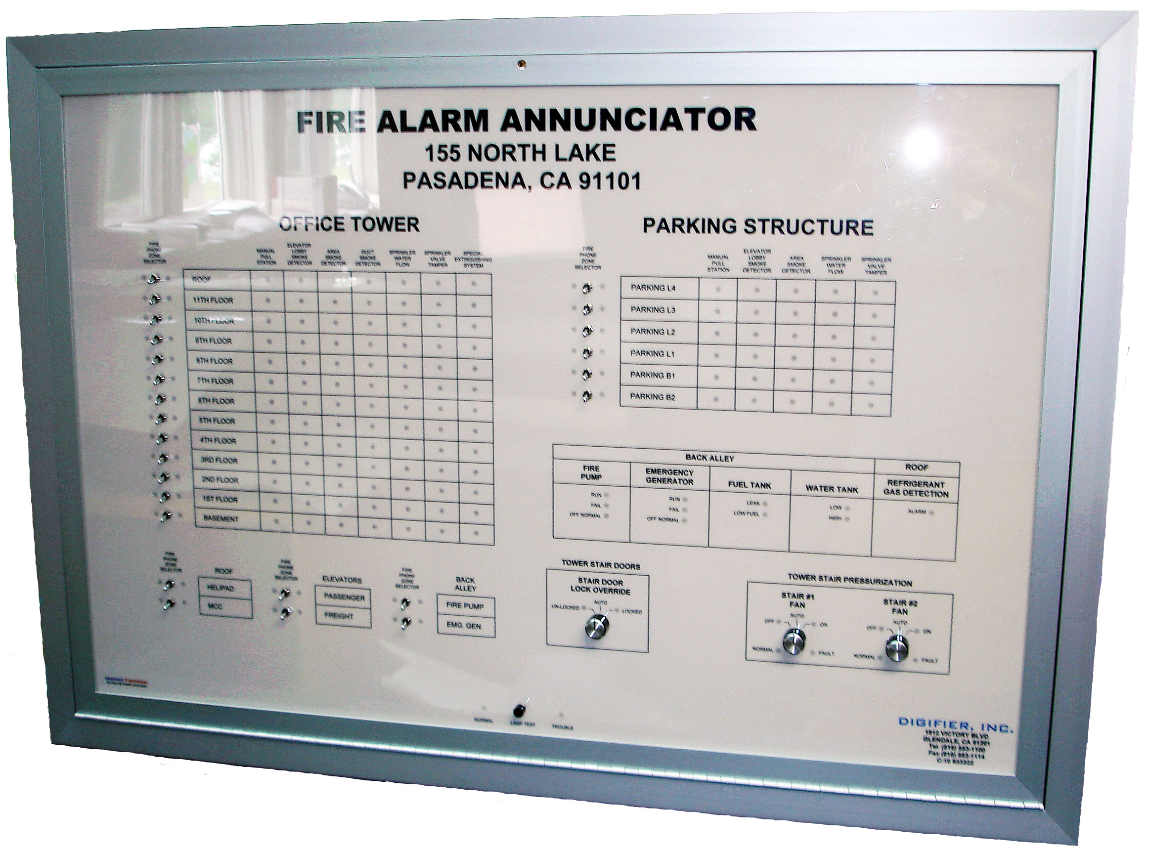
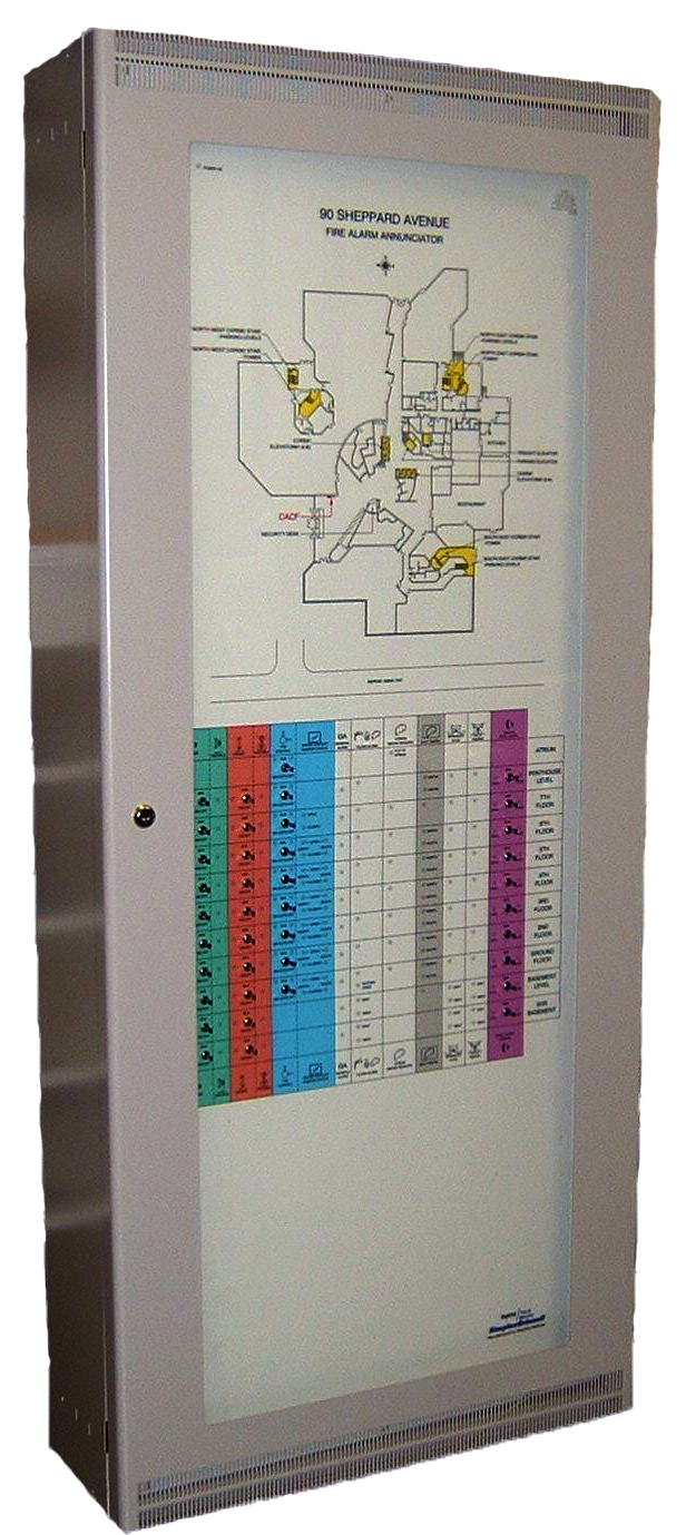
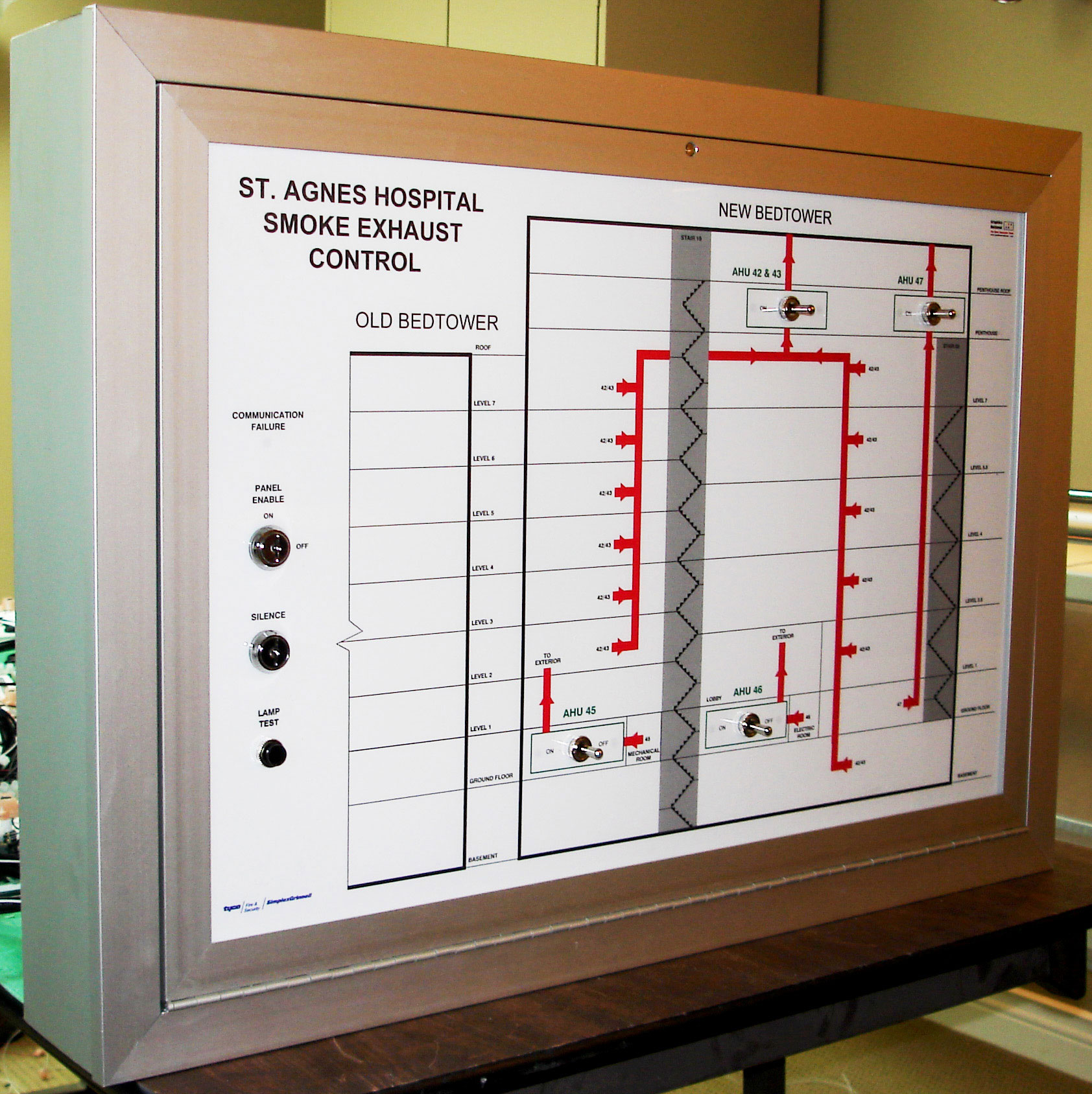
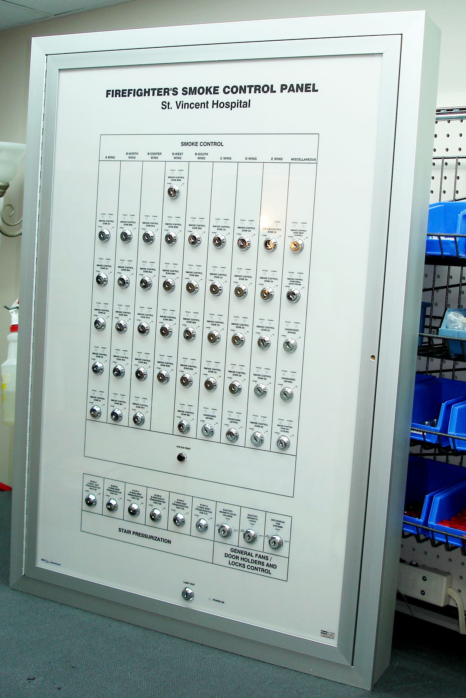
Graphics National Firefighters Smoke Control Stations/ Smoke Extraction Systems are designed for use in high-rise buildings and other facilities to manually control the fans and dampers designated for smoke removal during a fire emergency. The panel is designed to work in conjunction with fire alarm and control systems that provides clear indication of the status and operation of the dampers and smoke control fans for responding fire department personnel.
ON-AUTO-OFF fan control and OPEN-AUTO-CLOSE damper control is accomplished with three position rotary switches or toggle switches. Status LED indicators show the following conditions:
WHITE - fans, dampers - ‘normal’ status.
RED - fans, dampers - ‘off’ or ‘closed’ status.
GREEN - fans, dampers - ’on’ or ‘open’ status.
AMBER - fans, dampers - ’fault’ status.
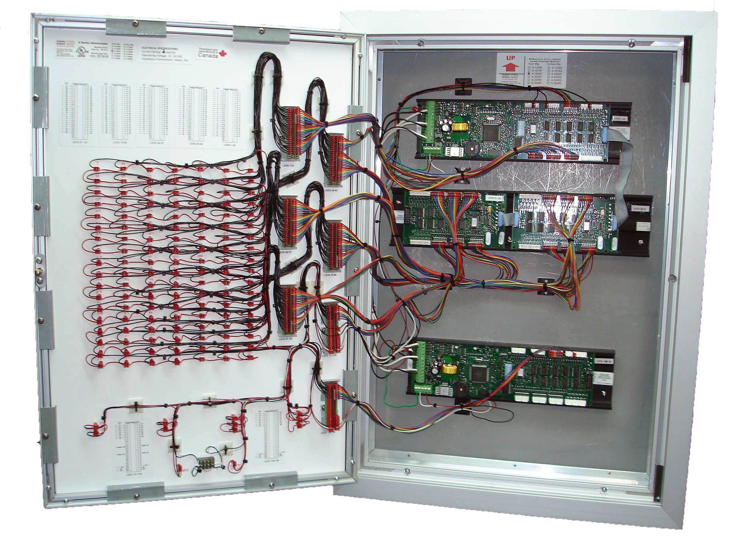
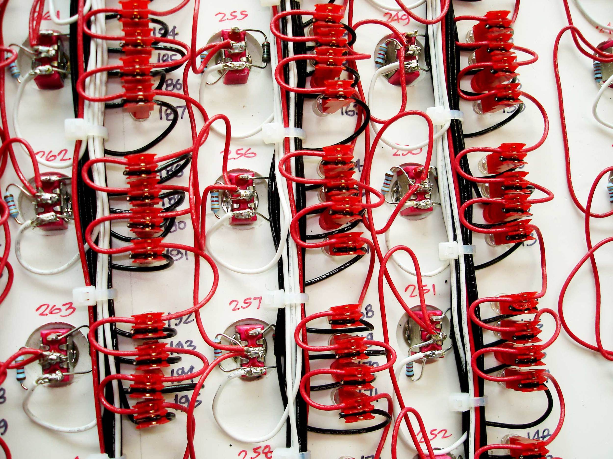
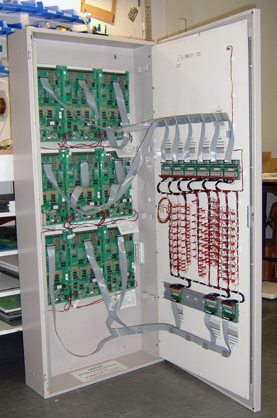
The switches and LED's are wired to customer supplied electronics or terminal strips which are sub-plate mounted in the enclosure. A push button switch is supplied for testing the LED's.
FEATURES
- UL 864 9th edition, UUKL & UUKL7 (Canadian) listed Firefighters Smoke Control Station/Smoke Purge Control
- California State Fire Marshal listed.
- Dampers and Fans controlled with H.O.A (Hand, Off, Auto) switches.
- Status indication LED’s showing position of Damper and Fan switches.
- Quick and easy graphic changes.
- Quick-connect ribbon cables connect to customer provided driver modules.
- Anodized aluminum cabinets available in multiple sizes.
- Low profile cabinet for ‘Flush’ or ‘Surface’ mounting.
- Security cylindrical door lock.
- Customer provided LED driver modules mount onto sub-plate.
- UV fade-resistant graphic inks.
- Lexan protective front.
OPTIONS
- Master Enable Key Switch to operate H.O.A. switches.
- Colored-coded graphical areas like zoning, stairways, shafts, air ducts etc.
- White or Black graphic background colors. Custom colors available.
- Custom cabinet sizes available upon request.
- Multiple AutoCAD font styles and linetypes available.
- Common control switches available: Pushbutton, Keylock, Toggle, Rotary, Rocker.
- Piezo audible trouble sounder.
ELECTRICAL SPECIFICATIONS
- LEDs: Rated 20 ma, 10 ma optional.
- Switches: Push Button, Toggle, Rotary, Rocker & Keyed
- Resistors: 680 ohm 1/4 watt, 1.2 K 1/2 watt. and 2.4K 1/2 watt.
- Operating Input voltage: 12-24 VDC
- Mounting and wiring of customer provided driver assemblies.
CABINET FEATURES AND SIZES
- Heavy duty anodized aluminum cabinets.
- Cabinet assembly consists of three parts: Door, Frame and Back Box.
- Door is attached to Frame via a left hand piano hinge.
- Electrical Contractor to punch own holes for incoming conduit.
- Customer provided driver assemblies mount onto metal stand-offs and screws pre-installed in back box.
- Graphic is securely mounted to door by means of metal clips and screws.
- Cabinets can be mounted vertical or horizontal.


